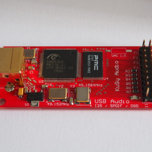
In the last months we have been working on a custom digital interpolation FIR filter implemented on an FPGA for old R-2R DACs. Our digital filter works in a similar way to well known DF1706, SM5847, PMD100, and so on. However, its ability to reconstruct and attenuate a signal is way beyond those. In fact, if you are a fan of NOS or in general you do prefer old R-2R DACs this project might turn your world around regarding the sound of digital filters.
The filter contains 8192 coefficients and it interpolates the data by a factor of 16 times (e.g. 44.1 kHz to 705.6 kHz and 48 kHz to 768 kHz). It has several FIFOs built in since its core is running asynchronously at 225 MHz while the MCLK on its I2S input is used only to clock data out of FIFO and to create LE (latch enable) signal for the DAC. This kind of approach ensures that the jitter relies only on the provided MCLK signal.
This digital filter does always interpolate to 705.6 kHz and 768 kHz (an integer factor of the input) and accepts data up to 768 kHz / 32 bits. In order to do that it works like a sample rate converter, so it interpolates and decimates at the same time without the need to skip any kind of interpolation phases (on a side note: segmented interpolation e.g. in PMD100 dictates three different sets of coefficient for each segments which interpolates incoming data by a factor of 2 resulting in total of 8x interpolation rate if the signal goes through all of them).
It should be noted that along with huge amount of coefficients (8192) this digital filter incorporates multiply-accumulate units of 32×35 bits wide. It means that the input data word is fully accepted up to 32 bits (without any truncation for that matter) and coefficients are quantized on 35 bits resulting in unmatchable accuracy of the math it does to calculate the output sample.
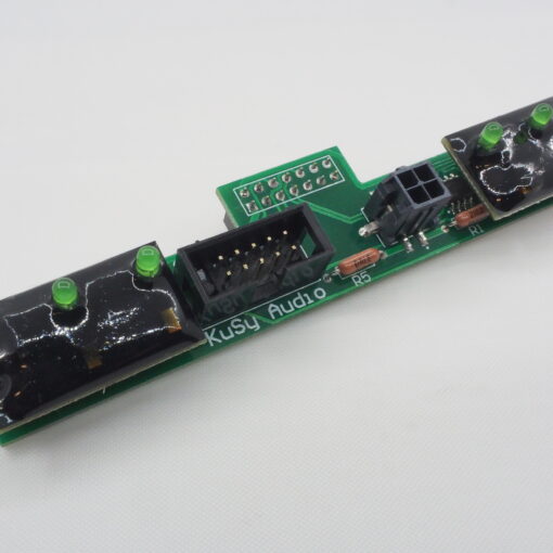
Our digital filter can drive PCM56, PCM58, PCM63, AD1860, AD1861, AD1862, AD1864, AD1865, PCM1702, PCM1704 and similar DACs up to 768 kHz. Considering the fact that datasheet of those DACs might indicate that operation at such high frequencies is unlikely to be supported in normal conditions you might ask how is that possible? The filter contains a self reconfiguratable oscillator which sets its frequency depending on the output length (16, 18, 20 or 24 bits). It means that the output bit clock (CLK) is running fully asynchronously from the LE (latch enable) signal which is generated by dividing the provided MCLK signal. Sample is latched without any jitter introduced by the oscillator itself which on its own operates at independent frequency to be able to transfer the sample into the DAC in specified limits. In fact, the filter contains 3 sets of FIFOs (6 FIFOs for both channels) – one in its input (I2S) before transferring samples to its core, another one on the core output and the last one for the final oscillator to clock data into the DAC. Besides all of that this technique introduces a quiet zone after the latch signal goes down, so it gives DAC some time to settle down with its output before clocking in another sample.
ROM jumper decides which type of filter should be loaded during boot process. There are two filters available, one is linear phase and the other one is a minimum phase. Both of them have total of 8192 coefficients.
Price: 250 EUR excl. VAT

Digital Interpolation Filter (FIR) Digital Interpolation Filter (FIR) Digital Interpolation Filter (FIR)